RLCS V4 Clientside
Clientside is used by the RLCS Control operator to control motorized valves and ignition. Clientside is a relatively simple system composed of a SRAD PCB, a LCD module and several missile switches. Additionally, it exposes a USB port which allows it to send data to a computer for plotting and logging. Clientside contains a set of missile switch, each match to a motorized valve.
Refer to RLCS v4 page for internal electrical connection diagram.
Requirements (Clientside)
Req. ID |
Description |
Justification/Parent Requirement |
|---|---|---|
MECH. 1 |
System shall be in a waterproof(IP64) case |
We don’t want electronics get wet to a computer with “unlimited” power source, so it should be priority |
MECH. 2 |
System shall have a keylock switch on the face plate |
For arm/disarm system |
MECH. 3 |
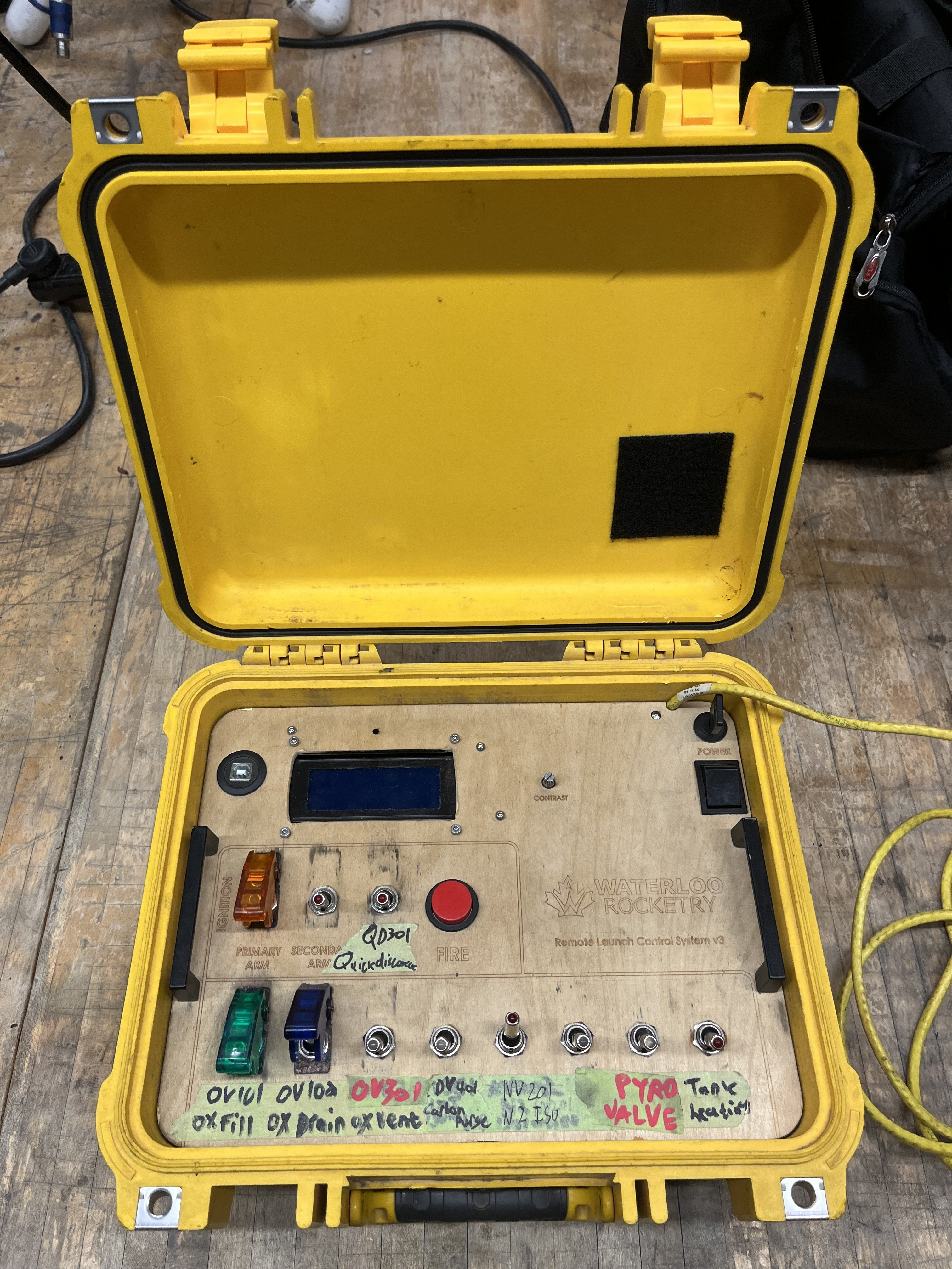
System shall have 12 missile switchs with LED lights, should have 16 switches, and two fire buttons. Which each fire button shall be paired with a switch, the switch would be used for arming the corronding fire button. |
10 valves/tank heating, 1 ignition arm and 1 injector arm. One fire button is used for ignition and the other button is used for pyro valve. LED lights for indicate if system’s armed |
MECH. 4 |
System shall have a 20x4 character LCD display, should have 40x4 LCD display(may be made of two 20x4 displays) |
RLCS Operator can monitor system |
MECH. 5 |
System shall have a red/green multi colour LED |
RLCS Operator see if system is connected to towerside |
MECH. 6 |
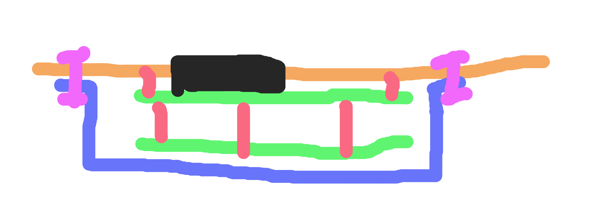
System should have a plastic case over electronics on the back side of the face plate (refer to diagram below) |
Protect electronics |
MECH. 7 |
All components shall be securely mounted on face plate, all wire be properly strain relieved |
? |
ELEC. 1 |
System have a Ethernet connection with RJ45 connector |
For communicate with towerside GLS board through local network |
ELEC. 2 |
System shall have a Type B USB port |
For get power from another device, and optional data logging |
ELEC. 3 |
System shall be able to power from the USB port(ELEC.2) or a 3S LiPo battery |
Redundant power supply |
ELEC. 4 |
LCD display and Clientside board should be stacked verticallly |
Have a stable electrical connection and mechanical mounting |
ELEC. 5 |
Each individual missile switch shall have it’s own ground connection to Clientside board |
Just in case ground wire breaks, it would only affect one switch |